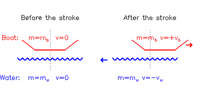
Consider a boat before and after a stroke.
 |
Before the stroke, total momentum p = 0,
since everything is at rest.
After the stroke,
total momentum: p = mbvb -
mwvw = 0
because the total momentum can't change (Newton's 2nd Law).
E.g. for a boat+crew mass mb = 100 kg (i.e. a single sculler) to accelerate from rest to vb = 1 m/s, requires either mw= 10 kg water to be accelerated to vw = 10 m/s, or mw = 20 kg water to vw = 5 m/s, or any other combination of mw and vw that gives the product mwvw = mbvb = 100 kg m/s.
During the normal stroke (i.e. with the boat already moving) it is less obvious that water is moved backwards in order to keep the boat moving forwards since the blades appear to 'lock' in where they are placed, but if you look at the puddles when the blades are extracted it's clear that water is moved. There has to be some slippage in order to accelerate the boat, although, from energy considerations (section 3), this should be made as small as possible.
So what about if you push off the bottom of the river, or a series of poles planted along the river bank, rather than the water? (I hear you ask). Well, in that case the whole planet moves backwards instead, and some slippage still occurs (as detected by a very pedantic spaceman with implausibly precise measuring equipment).
Skin Drag is proportional to the square of the velocity, so assuming that the Skin Drag dominates, the total resistance R can be written as
| (2.1) | R = a.v2 |
To maintain a constant velocity, the force applied must equal the resistance so there is no net acceleration or deceleration (Newton's 1st Law, actually, just to complete the set). Hence the average power P required (=force x velocity) is
| (2.2) | P = a.v3 |
| (3.1) | U = ½mbvb2 + ½mwvw2 |
Then the two examples give different results.
If mw=10 kg and vw=10 m/s,
| (3.2) | U = 0.5 x 100 x 12+ 0.5 x 10 x 102 = 50 + 500 = 550 Joules |
but if mw=20 kg and vw=5 m/s,
| (3.3) | U = 0.5 x 100 x 12 + 0.5 x 20 x 52 = 50 + 250 = 300 Joules |
This kinetic energy represents mechanical work performed by the rower, but in the first case they have to perform almost twice as much work as in the second just to achieve the same speed.
To achieve a given increase in boat speed, it takes less energy to move a large amount of water slowly than a small amount of water quickly. This is the basic argument in favour of 'bigger is better' spoon sizes, and also for not washing out.
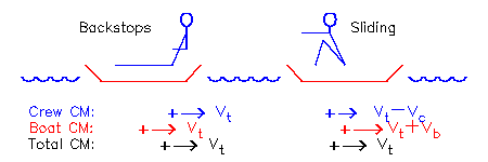
If a crew, mass mc, is sitting still at backstops in a boat, mass mb moving at velocity vt, the total momentum of the system is mcvt + mbvt
If the crew then start to move sternwards at -vc relative to vt, the boat must move bowards at a different relative velocity vb to conserve momentum:
| (4.1) | mc vt + mbvt = mc(vt-vc) + mb (vt+vb) |
| (4.2) | mc vc = mb vb |
 |
If the crew are 80% of the total mass (i.e. mc is 4/5 of mc + mb), then mc = 4 mb so vb = 4 vc. If the crew move sternwards at vc=0.2 m/s, the boat will move bowwards at an extra 0.8 m/s. In 1 second it looks to the crew that they've moved 1 m towards the stern of the boat, but to an outsider it looks like 80 cm of that movement was the boat moving towards the crew.
This is why the bows of a boat appear to surge after the finish of a stroke: although the blades have been extracted and are no longer accelerating the CM of the whole system, the crew's movement off backstops accelerates the hull forwards by an equal and opposite reaction.
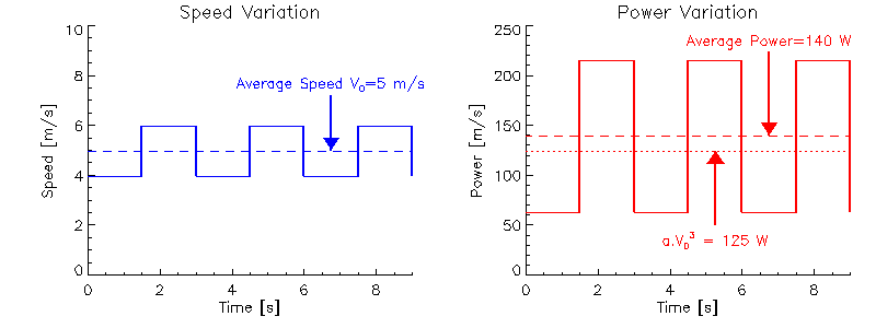
If a crew rows 1 minute at 4 m/s, and then 1 minute at 6 m/s, the total distance they cover is 60 x 4 + 60 x 6 = 600 m. From Eq.(2.2), assuming a = 1 kg/m to keep the sums simple, the total work W required (= power x time) is
| (5.1) | W = 60 x 43 + 60 x 63 = 16800 Joules |
and the average power over the two minutes (= work / time) is 140 Watts.
Suppose the same crew just rows 2 minutes at a constant 5 m/s. They will
cover the same distance as before, but this time the total energy required
is different
| (5.2) | W = 60 x 53 + 60 x 53 = 15000 Joules |
so the average power is also reduced, = 125 Watts. So they've used less average power (or less total energy) to cover the same distance in the same time. This means it is more energy-efficient to keep the same pace throughout a race (or on an erg) rather than, for example, start fast and slow down, or start slow and speed up.
 |
Since skin drag resistance (Eq.2.1) depends on the hull speed rather than the speed of the total centre of mass, the same arguments apply to the variation in hull speed during a stroke (Figure 5.1).
If the hull spends half of each stroke at 4m/s and half at 6m/s it is less efficient that keeping the speed constant at 5 m/s (you get exactly the same answer as above if you split the one minute piece into 60 separate 1 second pieces interspersed with 60 x 1 second pieces at the other speed). Therefore it is also undesirable to have too much variation in hull speed during the stroke (characterised by the bows or stern 'bobbing' up and down excessively).
In 'sliding rigger' boats the sculler's seat is fixed to the hull, but the stretcher and riggers are connected and free to slide back and forwards on bearings. With the sculler no longer sliding up and down, the variation in hull speed through the stroke is reduced, so these boats are theoretically more efficient (ie go faster for the same power). Since these boats are now banned, the theory presumably worked, although not necessarily just because of the skin-drag arguments (wave drag is also reduced).
Boats float because the downward force due to gravity is exactly matched by the upward force due to buoyancy. Gravity acts as if the total mass were concentrated at single point, known as the centre of mass, or centre of gravity (CG). Buoyancy forces also act at as if applied at a single point, known as the centre of buoyancy (CB). The CB coincides with the CG of the displaced fluid, which is not the same point as the CG of the floating body itself.
As the body rolls, the CB moves relative to the hull. For example, in Fig.6.1, when the hull is upright the CB lies along the dashed line, but if the hull is rolled anti-clockwise (as in the figure) the CB lies along the dotted line. The intersection of the vertical lines (buoyancy forces) through the CB at various roll positions is called the metacentre. If the submerged hull-shape has a circular cross-section (ie cylindrical hulls), the metacentre (M) is simply at the centre of curvature.

|
| Figure (6.1) |
Whether a body floats stably or unstably on the water depends on the relative positions of the metacentre and the centre of gravity.
The left figure shows the case where the M and CG coincide. At any roll angle, the buoyancy force is always directly underneath the gravititional force and no net turning moment results, hence it will sit an any angle it is placed: 'neutrally stable'. An example of this is a floating cylinder, where the CG and M both coincide with the central axis.
The middle figure illustrates the case of a racing shell. The submerged hull is near semi-circular (to minimise surface area:volume displaced for a given waterline width), hence the metacentre lies close to the waterline. However, to achieve an efficient rowing stroke, the crew has to be seated several inches above the waterline, so CG (ie mostly that of the crew) lies above M. If the boat rolls anti-clockwise, the buoyancy continues to act upwards through M, but gravity acting downwards at CG has now moved to the left so an anti-clockwise turning moment is generated which reinforces the roll - the whole system is intrinsically unstable (if you don't believe this, take the oars out and see how long you stay upright).
The right figure shows CG below M, so any anti-clockwise roll results in CG moving right relative to M to generate an clockwise restoring moment so the boat is stable. An example is a canoe with the canoeist siting low in a wide hulled boat.
Note that stability is only determined by the relative positions of the centre of gravity and the metacentre. It is quite possible to achieve stability for an oarsman sitting above the waterline by using a hull with a shallower curvature (raising the metacentre to the centre of a larger diameter circle - see Fig. 6.2). This is why training boats are more stable than racing boats. The disadvantage is the increase in surface area for the same displacement, hence increased drag.

|
| Figure (6.2) |
So why is it easier to balance a moving boat? Two reasons:
The oar acts as a lever which, in the boat's frame of reference, appears as in Fig (7.1) as a Class 1 Lever:
 |
The arrows show the forces on the oar. The forces on the boat (at the pin and stretcher) are equal and opposite to the forces on the oar at the fulcrum and handle respectively, leaving a net force L (downwards in the figure). The propulsive force applied to the water is equal and opposite to the load on the spoon, also L (upwards in the figure). Hence the forces on the boat and the water are equal and opposite.
For a given Effort E, the value of the Load L is determined by the ratio of lengths b and a
| (7.1) | L = E. (b/a) |
Since, for a normal oar, a is larger than b, the force appearing at the blade is less than the force applied to the handle. If this doesn't seem a good idea, remember that the distance moved by the blade is correspondingly greater than the distance moved by the handle, so that the Work W done at either end of the oar, defined as the product of (Force x Distance), remains the same. If the oar is moved through an angle y, the distance moved by the handle is b.y, and by the blade a.y, so the work done at each end of the oar is:
| (7.2) | handle: | W = E.b.y | |
| (7.3) | blade: | W = L.a.y = E.(b/a).a.y = E.b.y | (using 7.1) |
To an outside observer (e.g. a FISA official standing on the bank) this situation looks quite different - the stationary part (=fulcrum) appears to be the blade rather than the gate, giving the following Class 2 lever:
 |
In this configuration the Load is applied at the pin and given by the ratio of length a+b to length a:
| (7.4) | L = E.(a+b)/a = E + E.(b/a) |
In this case the oar amplifies the force applied at the handle. But note that the forces and directions along the oar are the same as in Fig. (7.1) (the 'fulcrum' and 'load' are just relabelled) so that the forces on the boat and on the water also remain the same. This is actually a general principle:
Calculated forces are the same in any frame of reference moving at a constant speed.
Although the 'stationary blade' frame (Fig. (7.2)) is preferable from the coaching point of view (e.g. teaching rowers to lever the boat past the end of the oar rather than pull the blade through the water), the 'moving boat' frame (Fig. (7.1)) has easier maths, so we'll use that when discussing gearing in the next section. The answers will be the same in any case.
Unfortunately, the load and the effort on an oar aren't applied at simply defined points so the gearing is conventionally expressed in terms of lengths which can be conveniently measured.
 |
The distance a is usually taken as the oar outboard length (Fig. 8.1), measured from the tip of the blade to the outboard side of the button. However, this in turn is usually expressed in terms of the inboard length (~115cm), which is easier to measure, and the overall length (~375cm), which is (usually) fixed (a~375-115=260cm).
The distance b is approximated by the span, also known as spread or T.D. ('Thwartship Distance') which, for a sweep-rigged boat is the distance between the centre of the pin and the mid-line of the boat (NB Span for sculls is defined as double this, ie pin-to-pin distance). Note that b isn't defined by the inboard length - it is assumed that the rower effectively applies pressure on the oar above the centre line of the boat, not at the tip of the handle.
To change the span requires moving the pin out (easier) or in (harder) and also has the effect of changing the arc length rowed. The details depend on rigger design, but usually requires a major rigging session.
There are several methods for changing the gearing via the outboard length. In increasing order of time required, these are:
To find the equivalent change da in outboard a that leaves the gearing (a/b) unchanged after a change db in span b:
| (8.1) | a/b = (a+da)/(b+db)
| (8.2)
| 1 + db/b = 1 + da/a
| (8.3)
| da = (a/b).db
| |
Since a is ~260cm, b is ~85cm, (a/b) is about 3, which is the usually quoted factor for equating changes in span to changes in button position. For example, increasing the span by 1 cm should 'feel' the same as moving the buttons out 3 cm.